Machining Function
Added Function to Specify STL Geometry for Machining Geometry
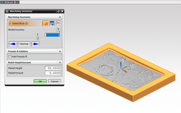
You can specify an STL Geometry for the machining geometry and output a tool path.
STL geometry registered as machining geometry in FFAUT are also imported into the FF Simulator (FF/SIM).
Supports STK File Setting Function When Lens Barrel Tool is Selected
When you have selected the Lens Barrel Tool, you can set the STK file in the following configuration screen.
- Contour semi-finish
- Contour finish
- Projection machining
The [Contour Semi-Finish], [Contour Finish] and [Projection Machining] settings in List Display Edit now support the STK file settings when the Lens Barrel Tool is selected.
Improved Plane Auto Recognition Function
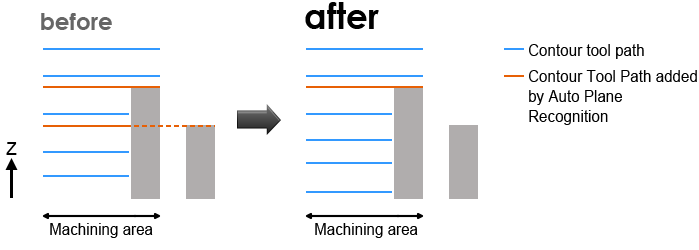
The previous [Plane Auto Recognition] function detected horizontal planes outside the machining area, which resulted in tool path output even at unwanted contour levels.
The function has been improved to recognize only the horizontal planes within the machining area and output an efficient tool path.
Tool Path Output Comparison
<2D Route Machining>Supports Selection of Multiple Curves
Previously, the registration of curve groups was selected one by one.
In FFAUT V.21, multiple selected curve groups can be registered to the basic curve at once.
The function has also been improved so that you can select multiple registered basic curves and edit the approach direction, minimum height and maximum height collectively.
Added Setting for Common Machining Start Point to Drilling
A common start point can be set for the start and end of drilling.
Since the start/end point of multiple drilling can be specified together, this setting saves time and remembering the settings is not required.
Operation
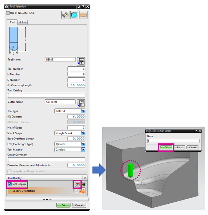
Addition of Tool Contact Point Display Function to Tool Selection Screen
From the tool selection screen, the tool geometry can be displayed at any arbitrary position on the model.
Tool Contact Point Display Function Supports Lens Barrel Tool
When a lens barrel tool is set, the tool contact point display function is available on the following parameter setting screen.
- MC Direction / MC Reference Point
- Area Parameters
- Interference Check Function
- Infeed Motion Parameters
Added Function to Automatically Acquire Information of Previous Machining Tool when Creating a New Corner R Machining
When creating a new Corner R Semi-Finish and Corner R Finish machining, the tool information for the previous machining in the same process (previous machining tool/finish allowance) is now automatically loaded.
When creating new Contour Semi-Finish Machining and Contour Finish Machining, the tool information for the previous machining of CR simultaneous machining is now automatically loaded.
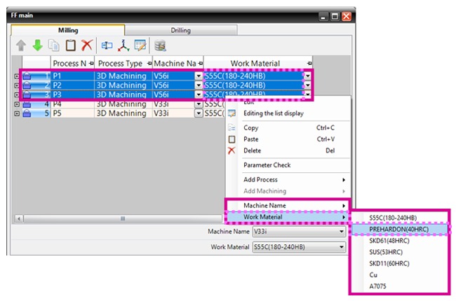
<FF Main Screen>Added Batch Change Function for Machine Name and Work Material
In this menu, you can change the “Machine Name” or “Work Material” of the selected process.
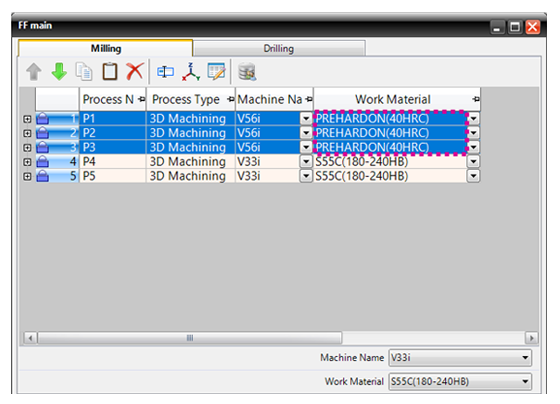
When multiple processes are selected, the machine names and work materials of multiple selected processes can be changed at once. Both [Milling] and [Drilling] are supported.
To change work material
Change results of the screen example
Added Function for Data Comparison to Editing the List Display Screen
In the [Editing the list display] screen, a function that allows you to compare parameter setting values for each set machining data has been added.
The comparison results are displayed in a list, and the parameter setting values of each machining data can be compared and the differences can be confirmed.
Machining data of both milling and drilling are supported.
Added Function to Automatically Acquire Setting Values when Data is Copied from the Template
You can define the mode to automatically acquire parameters such as machining geometry, blank geometry, machining area and finish allowance under specific conditions, when data is copied from the template.
Multiple patterns of the definition (mode) can be registered in advance. From the registered modes, the definition (mode) to be applied when the data is copied can be specified.
<Professional Data Output>Added Function to Specify the Fixture Data by the Layer Number of NX
The fixture data can now be specified by the layer number of NX. When professional data is output, the body data in the specified layer is output as the fixture model in STL file format.
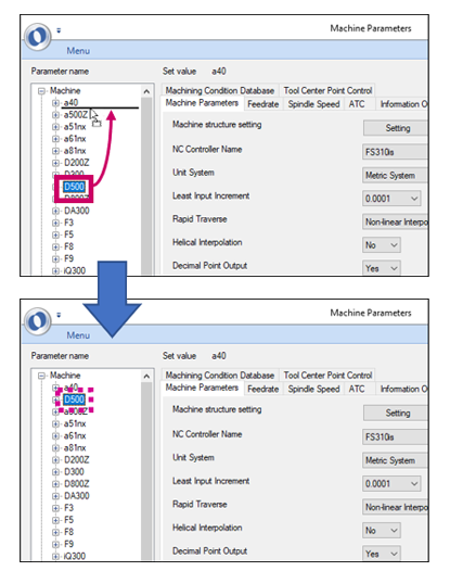
<Machine parametor>Added Function to Sort Machine Names to Setting Parameter Tree
Added Function to Sort Machine Names to Setting Parameter Tree The machine names can now be sorted by dragging and dropping them in the setting parameter tree of the machine parameters.
POST
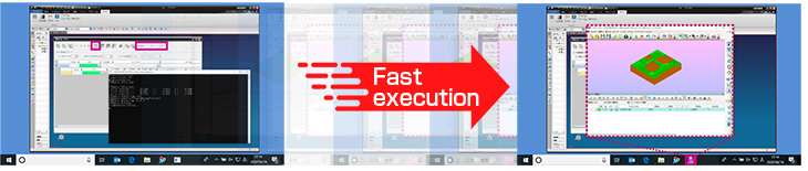
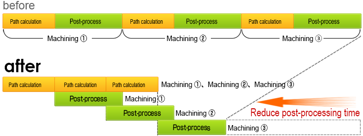
<FFPOST>Reduced Post Process Time
After completing the path calculation of the first machining, the path calculation of the next machining starts at the same time as the post process starts and the post process is performed in parallel.
This improvement reduces the post process time.
Post Process Sequence (individual calculations for multiple machining)
FF/SIM
Added Function to Select Machining Geometry and Blank Geometry Used in FFSIM
Simulations can now be run by specifying geometry registered in a layer.
When running a simulation with a machining geometry and blank geometry having modifications such as masked holes or extended faces, you can run the simulation as is by specifying the geometry after registering it to a layer.
Added Function to Automatically Run Simulation and Post Process after Path Calculation
Only by executing the path calculation, the simulation can be checked in FFSIM all at once.
The addition of this feature significantly reduces the number of steps required to run the simulation.
A function to automatically run post process along with path calculations has been added.