FFAUT V.25 New Function
Machining Function
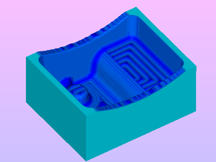
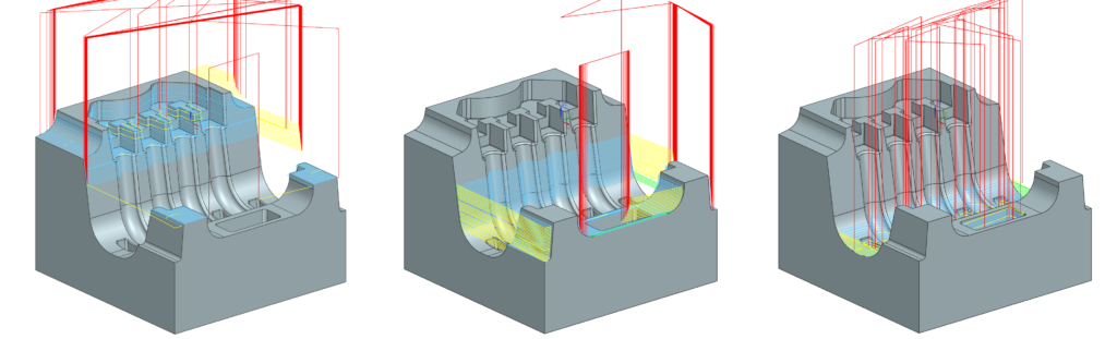
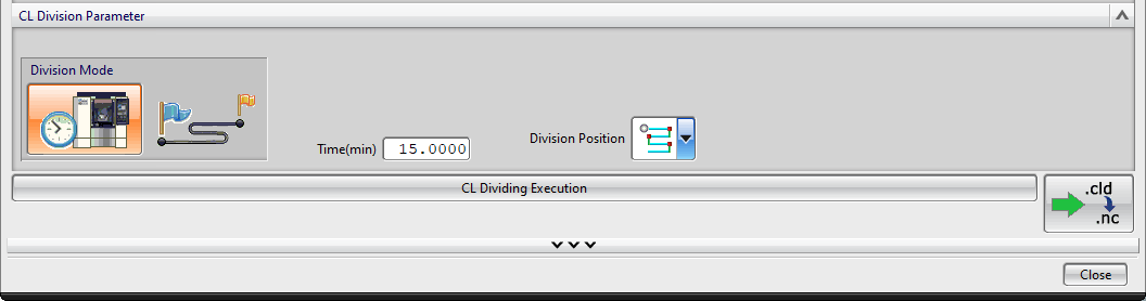
Toolpath Division by Cutting Time or Cutting Distance
During operations that take a long time (cutting distance), the tool life may be exhausted and the tool may break, causing the machinning surface to deteriorate. In such cases, the toolpath is divided and shortened. This function allows you to efficiently create a split toolpath.
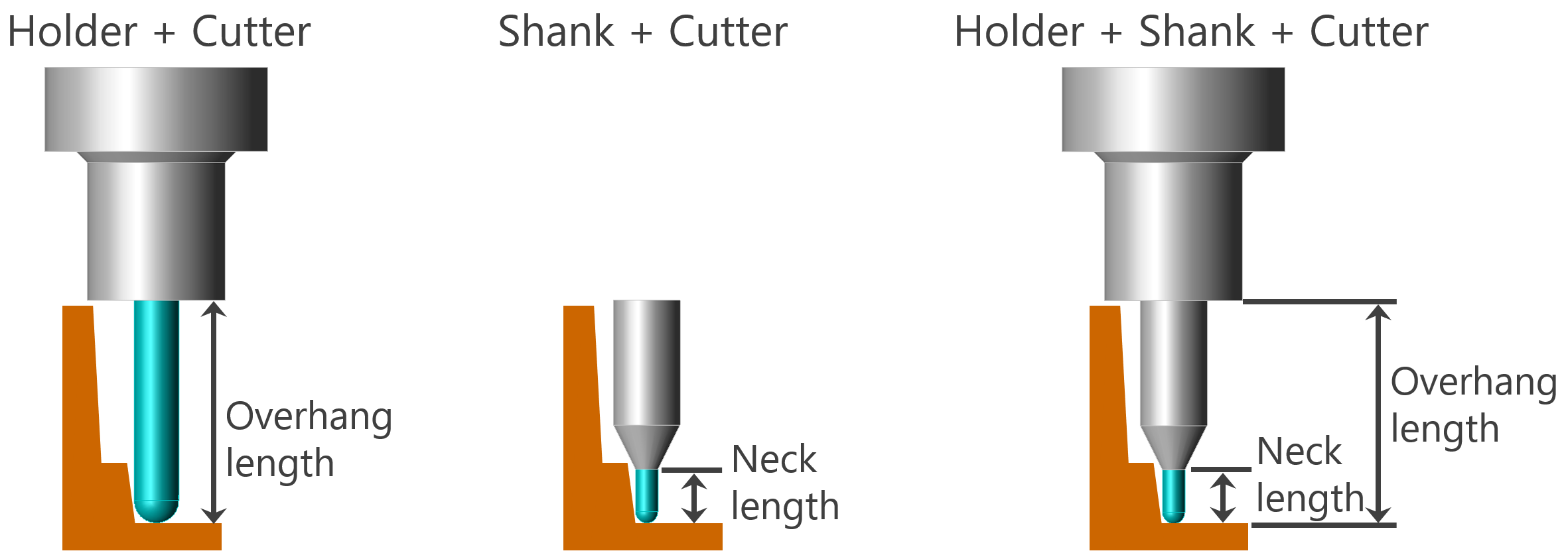
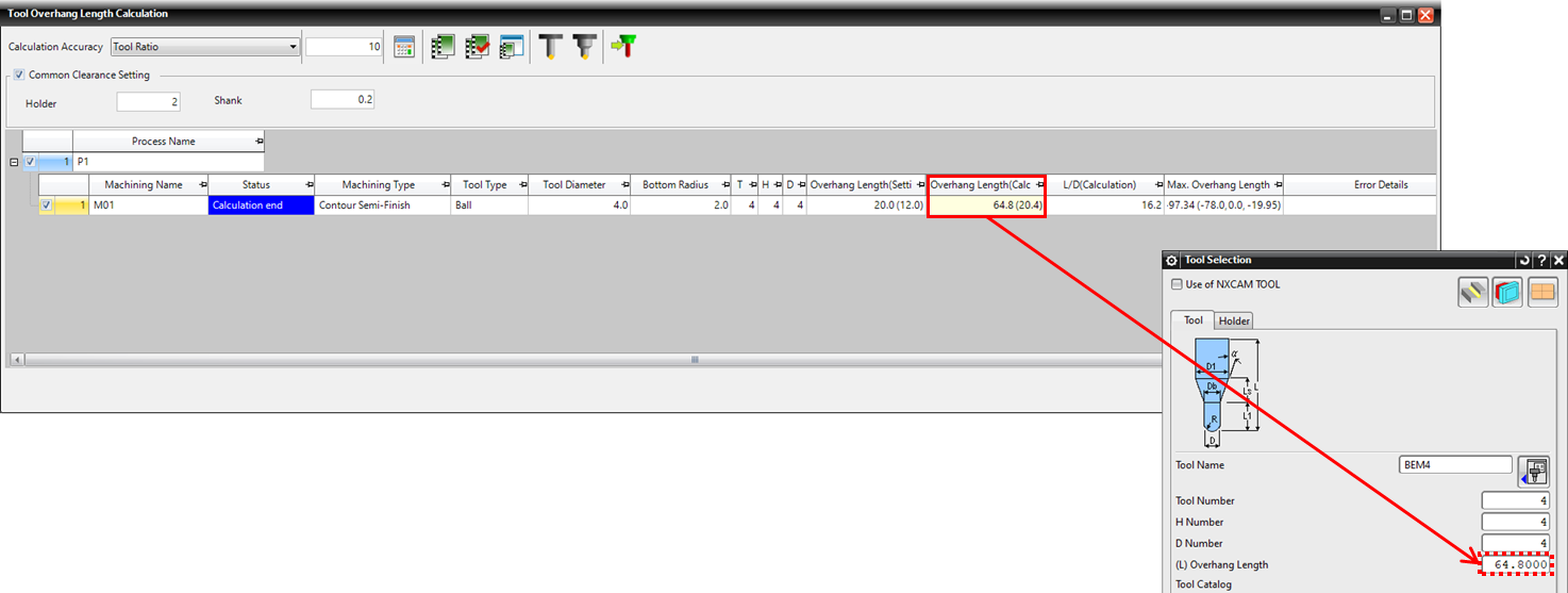
Calculating Tool Overhang Lengths That Do Not Interfere with the Machining Model
In the tool settings, it is necessary to select a cutter with a neck length that does not interfere with the model and set the overhang length. This function allows you to calculate the overhang and neck length of a cutter that will not interfere with the model being machined.
Defining the Toolpath Direction Angle Using Points or Faces on the Model
It is now possible to specify the direction of the toolpath using two points, tangents, or face normals on the model. This can be set when “One-Way” or “Zigzag” is selected for the toolpath motion in the following machining settings.
- Contour Rough machining
- Projection machining
- Contour Projection machining
- Flat Face machining
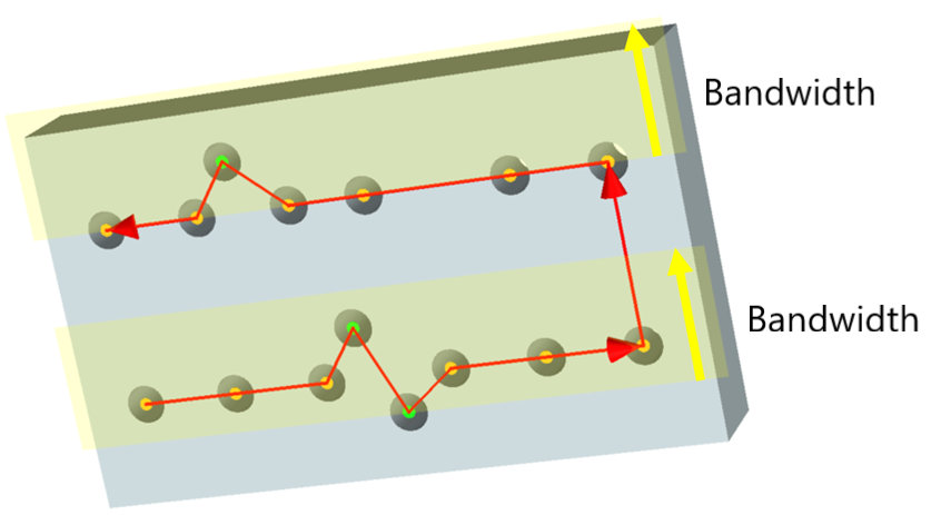
<Drilling> Drill Holes in a Zigzag Order
The previous Sort Hole Position function was limited to sorting in one direction. This function allows you to automatically sort in a zigzag direction based on the X or Y axis. In addition, you can include holes within a specified range (Bandwidth) in the drill order.
<Contour Machining> Constant Scallop Height Motion Can Be Used with Contour Spiral Motion
Constant Scallop Height Motion can now be used even when Contour Type is set to Spiral. This prevents material from being left over on flat areas, while also preventing the toolpath from becoming too narrow on the sides.
Operation
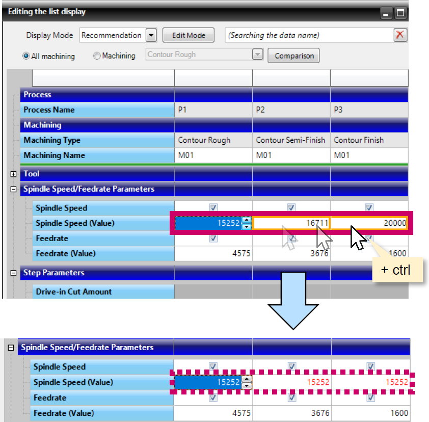
Improved Copying When Editing in List View
In the [Editing the list display], you can now “Copy settings by category” and “Copy settings to multiple machining data simultaneously”.
Output of the Setup Sheet for the ZOLLER Tool Measuring Machine
It is now possible to output a setup sheet file (.xml) that can be read by the ZOLLER tool measuring machine.
The ZOLLER setup sheet is a list of external tool ID’s (ID numbers) and their corresponding T numbers. The sheet can be imported and used by the ZOLLER tool measuring machine.
FF/SIM
Faster Display of Uncut Areas in CL Simulation
In the “Create Data (Details)” mode, the drawing time when moving or rotating the viewpoint has been greatly reduced.