Machining Function
Improved Uncut Part Machining for Flat Face Machining
In the previous version of FFAUT, a tool path was also output for the flat surface because the uncut part machining of flat face machining only supported the update of the uncut geometry.
In FFAUT V.22, in addition to the update of the uncut geometry, the difference between the machining geometry and the uncut geometry is also determined, and the tool path is now output only for the part that is uncut.
An example of reading the uncut geometry in flat face machining and outputting the tool path is shown below.
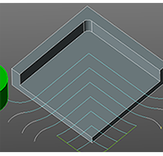
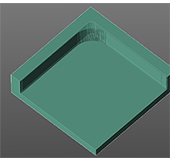
Uncut Part Machining for Flat Face Machining
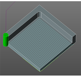
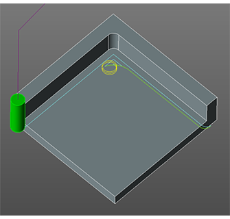
Tool path is output only for the difference between the machining geometry and the uncut geometry.
Changed the Setting Range of [Maximum cutting angle of inclination] for Round Insert FM
The setting range of [Maximum cutting angle of inclination] for Round Insert FM in the [Cutter edit] screen of Maintenance of Tool database has been changed to correspond to the specifications of various tool manufacturers.
Change in Setting Limitation of [Shank steps] for Pencil Neck Tool
Some of the limitations when setting the [Shank steps] of pencil neck in the [Tool Selection] screen have been removed to support the specifications of various tool manufacturers.
In FFAUT V.22, registration is now possible even if the “Shank Diameter” is set to a value smaller than the “Tool Diameter”.
Operation
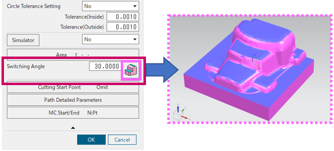
Addition of Switching Angle Preview to Contour Projection
The surfaces that are steeper or gentler than the angle specified in the [Switching Angle] parameter are displayed in different colors, allowing you to make settings while checking surfaces to be machined by Contour Machining and surfaces to be machined by Projection Machining.
Example: When the switching angle is 30º
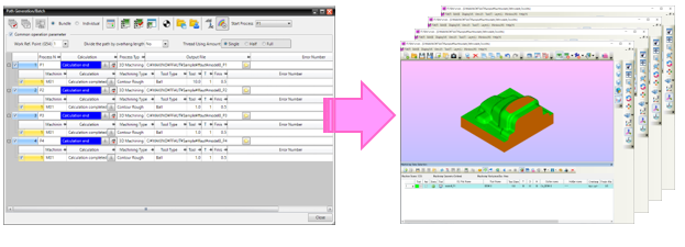
Addition of Function to the FF/SIM Automatic Run Function for Simulation of Data from Multiple Processes in a Batch
The Automatic run function of FF/SIM can now run simulations for both individual processes and multiple processes in a batch.
In addition, the user interface design of the automatic run function on [Path Generation/Batch] screen has been changed along with the update to this function.
Each process
A project is created for each process that is calculated and the simulation is run.
FF/SIM start(s) only for the number of processes.
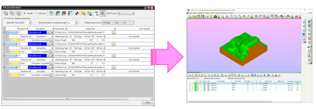
All processes *Default
The simulation is run with all the processes that are calculated as a project.
Only one FF/SIM starts.
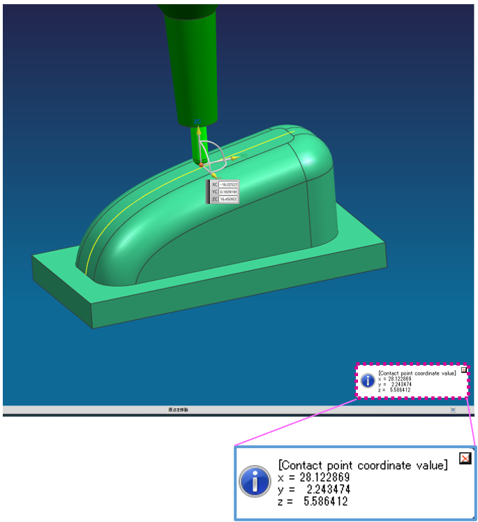
Addition of Function to Contact Point Tool Display for Displaying Coordinate Value of the Contact Point Between the Tool and Geometry
When using Contact Point Tool Display function, the coordinate value of the contact point between the tool and the geometry is now displayed in a message along with the movement of the drawing point of the tool model.
Addition of Function to Change the Order of the List Rows on the Tool Database Maintenance Screen
The order of the list rows can now be changed as required on the Tool database Maintenance screen.
FF/SIM
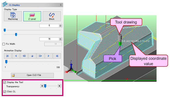
Addition of Function to CL Display for Drawing Tool and Coordinate Value Display
A function to draw the tool at the point on the CL path picked by the mouse click during CL display has been added.
In addition, the coordinate values of the point where the mouse cursor was rolled over on the CL path is also displayed.
Addition of Function to Display the Angular Deviation of Model in Different Colors on the Measurement Screen
A function is now provided to draw the angular deviation of a specified face or the entire model geometry in different colors.
This allows users to determine the angular deviation of the entire geometry at one time and use it as a reference for tool setting.
Improved Function to Display Measurement Balloon
A function to adjust the annotation balloon display to a size that fits within the screen has been added.
By using the [Fit of the measurement result] function, all annotation balloons can be moved to a position that fits within the screen in a batch.

Addition of Function to Measure the Cylindrical Area of Geometry
A function to measure the size of the geometry in the cylindrical area has been added, allowing the required values to be obtained efficiently.
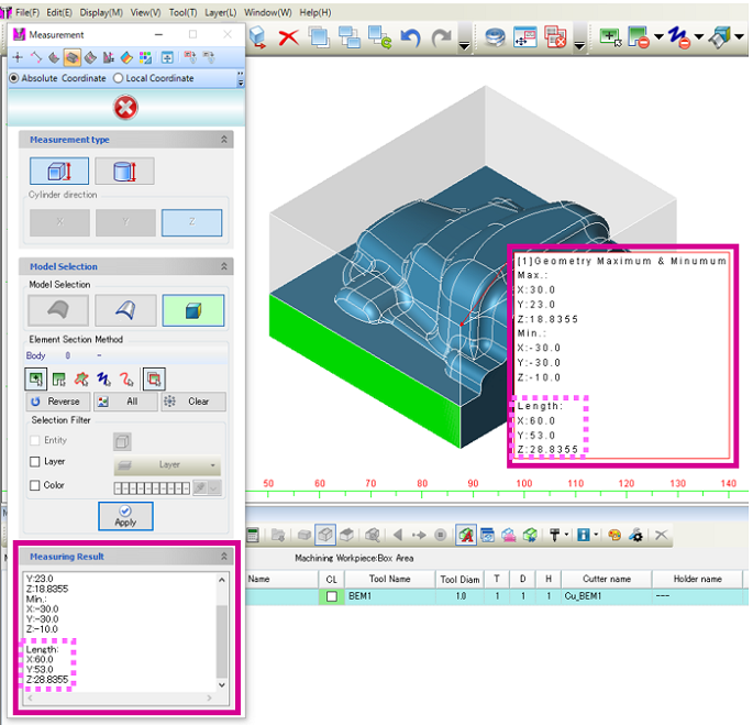
Addition of Measuring Result Type to
[Maximum and Minimum on Geometry] in [Measurement]
A function to display the “Length” has been added to the measurement result of [Maximum and Minimum on Geometry] in [Measurement] (Measurement type: box).
After measurement, the length of each side X, Y, and Z is displayed, along with the maximum and minimum values of X, Y, and Z for the previous box.
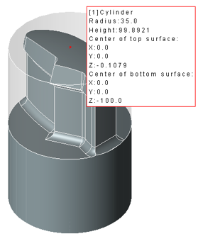
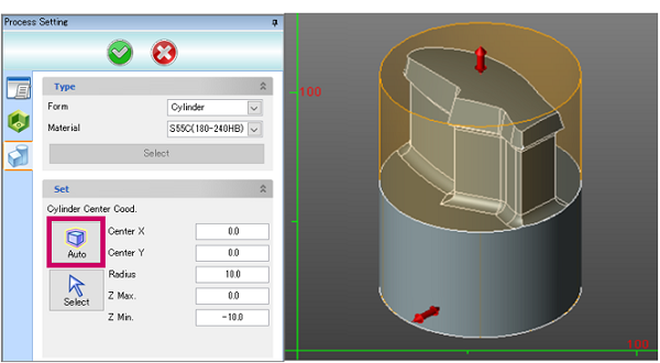
Addition of Automatic Geometry Acquisition Function to [Cylinder] in
Process Setting
In the same way as the automatic acquisition of [Box area], the cylindrical geometry can be automatically acquired and defined.
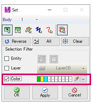
Addition of Multiple Color Selection Filter in Element Selection Screen
In the previous versions, filtering could be executed with only a single color, but with this new function, multiple colors can be specified for filtering.
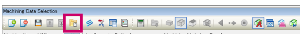
Addition of Function to Open the Save Location for Data with a Single Click
The [Open a designated folder] button has been added to the [Machining Data Selection] screen.
You can open the save-destination folder for the working file with a single click.