
Version comparison : V.23.0
Machining Function
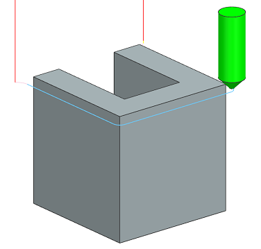
Added Light Chamfering Function to 2D Route Machining
Chamfer cutters can now be set for 2D Route Machining.
Settings have been added for light chamfering.
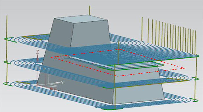
[Output Only to Plane Part] Function Has Been Added to the [Plane Auto Recognition] Function of Contour Rough Machining
If the [Output Only to Plane Part] function is used, a contour face cut machining path is output only for the surfaces that are automatically recognized as planes (red frame in the image below). This can reduce the machining time.
Added a Function to Automatically Set the Setting Values of [Minimum Uncut Detection] of Uncut Part Machining with a Percentage Value of the Tool Diameter
On the machine parameters setting screen, the initial values of [Min. Uncut Detection] of each machining can be now changed to a percentage value of the tool diameter.
Added a Function for the Automatic Setting of the Setting Values of [Area Detection Accuracy] of Contour Projection Machining with Automatically Calculated Values
On the machine parameters setting screen, the initial values of [Area Detection Accuracy] of contour projection machining can now be changed to automatically calculated values.
Improvement to Enable Setting the NC File Extension for Each Machine
The NC file extension to be output can now be set for each machine.
The setting items of [NC File Extender] of machine parameters have been moved from [NC Output Parameters] to [FFPOST PARAMETERS] of each machine.
Improvement to Enable the Setting of [Safety Mode at Hole ATC] for Each Machine
The setting items of [Safety mode at hole ATC] in the machine parameters have been moved from [NC Output Parameters] to [Machine Parameters] for each machine.
Added New Models to the Machine List of Machine Parameters
The following models have been added.
iQ500,V100S,v61,a71nx,a92,a120nx
The addition of the models are also reflected in the model name selection of the process data.
Operation
Improvement to the Setting Items of the Tool Cutting Edge Length Parameters
In FFAUT V.23, the value set for [Cutting Edge Length] in the [Tool Selection] screen is output to the tool data that is prepared in CSG Interface and Vericut.
Specific Half-Width Symbols Can Now Be Used for the Project Name in the Professional Data Output Screen
Improvement has been made to enable input of “- (hyphen)” and “_ (underscore)” to [Project Name] in the [Professional Data Output] screen.
FF/SIM
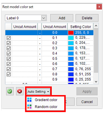
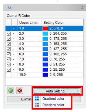
Added a Function to Set a Random Color for Rest Models and Corner R
When auto setting the setting color, select [Gradient color] or [Random color] from the pull-down menu of the [Auto Setting] button.
Changed the Initial Values for the Interference Check Condition of the Simulation Settings
Changed the check conditions of [Interference Detection Setting] of [Simulation Setting] to perform the interference check operation with the initial values.
Interference detection of following items will also be performed automatically when the simulation is executed.
- Collision check at cutter Rapid Motion
- Holder and Shank Interference Check
- Bite check of machining geometry
Other
Changed the File Format of FFAUT Help
Changed the format of FFAUT Help from an HTML file, which required a Web browser for viewing, to a chm format help file that allows direct viewing.
In addition to the table of contents, keyword search and a function to search by entering any word or phrase have been added, making it easy to search for the desired topic.