
Version comparison : V.18.0
3+2 axis Machining Function is providesd as standaed
The 3+2 axis Machining (formerly TiltMill) is provided as standard in FFAUT V.18.
The [Machining Direction and Reference Point] tab has been added to the [Machining Parameter Setting] screen. When 5 axis machines are selected, the [Machining Direction] screen will be displayed, allowing machining settings to be performed
Simulation(FF/SIM) is providesd as standaed
The Simulation (formerly FF/SIM) is provided as standard in FFAUT V.18.
Previous simulation detection functions and check functions have been significantly enhanced in [FFAUT V.18].
Screen designs and operability have been improved to enable using the functions more easily.
Machining Function
Enhancement in 3D Equi-Pitch
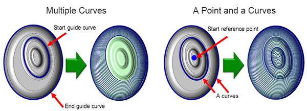
Close Machining with Multiple Guides
Multiple guide curves or a point and a curve(s) can be chosen.
A cutter path of the spiral motion along the eccentric shape can be created.
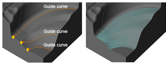
Open Machining with Multiple Guides
The tool path is generated by interpolating multiple guide curves that are specified.
“Every curve” shorten the machining time.
Because it is move less between the guide curves and it is intensively machining one of the guide curves.
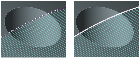
Averaging with the Maximum Block Length
This feature prevents the generation of a block of NC data for which the travel distance is too long.
As a result, tool motions in machining are averaged and the quality of the machined surface is improved.
Enhancement of Contour Machining Function
Added Z Spiral High Speed Function
Now supports high speed operation process when [Spiral] is selected as the operation type for “Contour Machining”.
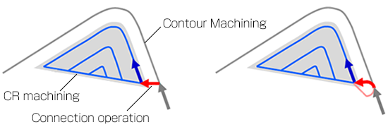
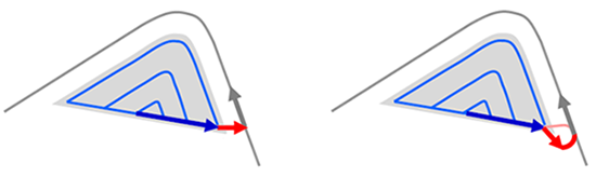
Improved Connection Operations in CR Simultaneous Machining
Corner R can now be added to the motion of connecting the tool path of “Contour Machining” and “CR Machining”.
Smooth operations on the machined surface prevent marks from being left on the geometry.
The purpose is to improve machined surface quality.
Left : With corner R: No , Right : With corner R: Yes
Contour machining -> CR machining
CR machining -> Contour machining
Enhancement of Contour Projection Machining Function
Added Z Spiral High Speed Function
Now supports high speed operation process when [Z Spiral] is selected as the operation type for “Contour Projection Machining”.
Enhancement of Corner R Machining
Improvement of Uncut Recognition Accuracy
The entire geometry can be finished while avoiding the tool load on the corner sections.
The path of contour line machining is output concurrently with corner R machining (contour).
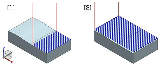
Enhancement of Flat Machining
Added Flat Face Machining/Flat Z Tolerance
The tool paths of [Flat Face Machining] can be output to planes with small curves and tilts.
- Amplitude in Z direction > Flat Z Tolerance : Paths are not output to curved surfaces.
- Amplitude in Z direction ≦ Flat Z Tolerance : Outputs paths to curved surfaces also.
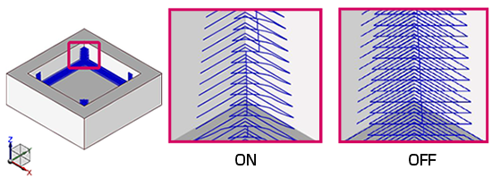
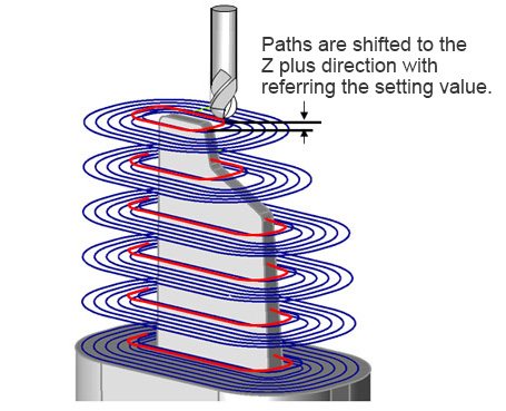
Additional functions in the thin rib processing
The function that the cutter path in the closest to the geometry is shifted to the Z direction is added.
The function can reduce the tool load at the closest area of the geometry and offer the better machining surface.
GO1 output in Drilling
The Machining data of G01 can be output.
(G73,G81,G82,G83,G85 and G89< only this option can be set as ON or OFF >).
Drilling can be done by even the machine cannot use the FANU canned cycle.
Supports drilling for High Accuracy Machining Time Prediction
[High Accuracy Machining Time Estimation] is now supported even for [Drilling].
Operation
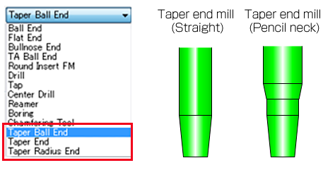
Tapered Tool Compatibility
The [Cutter edit] screen supports tapered tools.
The latest machining conditions of tool manufacturers can be imported, and tapered tools can also be referenced.
Simulation (FF/SIM Functions)
Temporary stop during collision check at cutter Rapid Motion
Setting “Temporary stop” when collision is detected in [Collision check at cutter Rapid Motion] has been made possible.
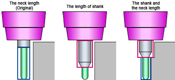
Overhang Length Calculate
Support for Pencil Neck
Shortest overhang length from the holder can be calculated in case of pencil neck type tool with [Overhang Length Calculate] function.
Able to find out the suitable tool easily.
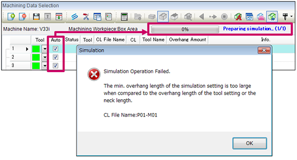
Error is displayed before calculation
If the [Overhang Length Calculate] setting is not appropriate, an error message indicating the cause will be displayed at the start of calculation.
If [Auto Execute] is ON, multiple machining lists are checked at the start of calculation and the cause of the error and “corresponding CL File Name” will be displayed.
Now, errors can be checked before calculation to eliminate unnecessary re-calculation time.
Improved Machining List
When [Overhang Length Calculate] is carried out, the background color of the [Overhang Amount] field of [Machining List] will change.
If longer than the tool setting, it will be displayed in “yellow”. If shorter, it will be displayed in “green”.
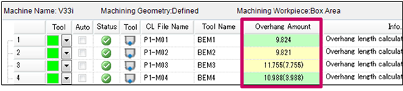
- White : If the [Overhang Amount] need not be changed.
- Yellow : If the calculated [Overhang Amount] is longer than the tool setting.
- Green : If the calculated [Overhang Amount] is shorter than the tool setting.
Add of Cutting Depth Calculation Function
Cutting Depth Check
A function which detects cuts deeper than the specified value and prevents collision into work has been added.
Damage to the tool and spindle can be prevented by detecting cuts exceeding the expected depths.
You can check the maximum cutting depth during machining.
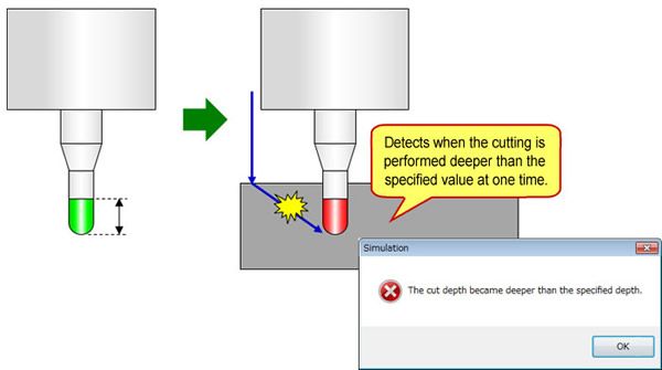
Results in an error when cutting depth above the specified value is detected, and information is output.
It does’t detect at drilling and fast-feed command.
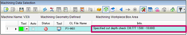
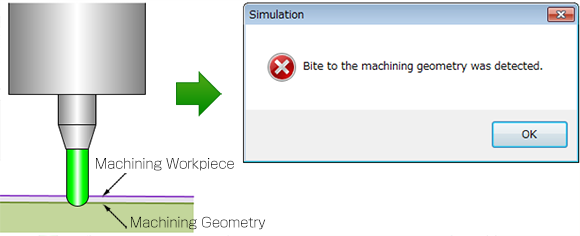
Calculates the Max. Cutting Depth
Outputs information on [Max. Cutting Depth].
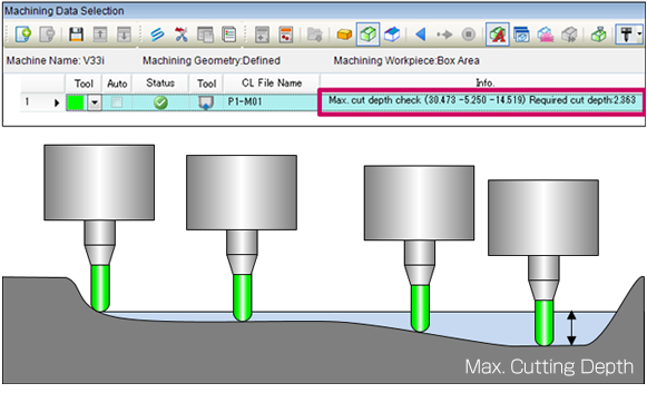
Addition of Machining Geometry Gouging Detection Function
Added a function to detect gouging when the simulated geometry gouges into the machined geometry.
Add of Cross Section Display Functions
A function to display the cross section of the simulation results has been added. This enables detailed parts to be verified more easily.
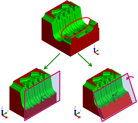
Right : Display by specifying the cross section direction, coordinates, and rotation angle.
Add of Cutting Results Display Function
The CL data with the interference and the position of interference are displayed on the screen.
This function checks the causes for interference with both values and on the screen to enable measures to be taken efficiently.
- CL File Name
- Tool Name
- CL Information
- Interference position
- Interference information list
- Mark display setting