Products
Standard Functions
Version comparison
![]()
Products
Version comparison : V.20.0
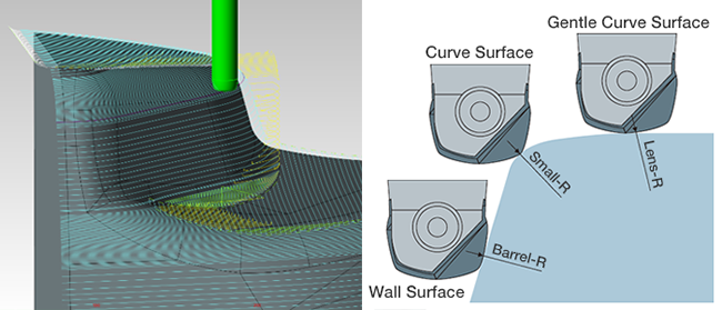
Machining FunctionLens barrel tool is now supported.
The lens barrel tool has gentle R at the bottom and side surfaces. Therefore, in machining, the step can be set to a larger value than when a ball end mill with the same tool diameter is used, resulting in shorter machining time.
Machining FunctionSupports Multiple Taper Neck Stages
You can now set a tool shank up to 5 stages. The tool shape that is closest to the actual tool can be registered, enabling a more accurate interference check of the shank.
| 1-stage shank (conventional) |
2-stage shank |
5-stage shank |
|---|---|---|
 |
 |
 |
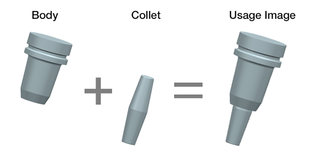
Machining FunctionSupport for Two Piece Holder
For the holder registration, the holder body and the collet can be used in combination, after separately registering them.
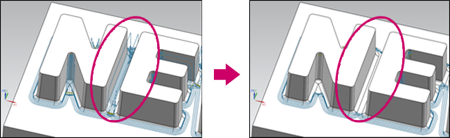
Machining FunctionContour Corner R
Groove Path Restriction Function
Uncut areas are determined if they are grooves and [Along-area] paths are restricted. In [Corner R Machining], the tool path of [Along-area] may be irregular at the grooves. This function solves this problem.
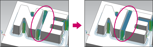
CR Machining Mode/Along-area
Tool paths are removed in the grooves.
CR Machining Mode/Contour + Along-area
Tool paths of [Contour] are output for the entire groove.
Add of Function to Suppress Path Output by Slope Angle
This function can be used in [Contour], [Along Area] and [Pencil] of CR Machining.
Until now, the tool path was output for the whole range specified in [Contour] and [Along Area], and tool path was created even in areas where the respective machining method was not appropriate (easy slope for Contour and steep slope for Along Area). Therefore, parameters and machining conditions had to be adjusted.
With this function, allows tool paths to be created only in the areas appropriate for each machining mode.
Change Default Values of Parameters
Initial value of clearance changed from 50% to 0% of Tool Radio.
The machining time is reduced by eliminating the output of the tool path that resulted in an air cut in FFAUT V.19.
At the same time, the default value has been changed to improve the uncut portion detection accuracy.
Change[High Accuracy Mode]check from OFF to ON
Generates a more accurate tool path based on the uncut geometry when [High Accuracy Mode] is turned to ON.
[High Accuracy Mode]:ON
[High Accuracy Mode]:OFF
Zigzag Motion Added to Z Drive-in Cut
"Zigzag" motion has been added to Z Drive-in Cut for Route and 3D Curve Machining.
The zigzag motion can be used to reduce machining time without escape motion.

Left figure:Z Drive-in Cut in one way , Right figure:Z Drive-in Cut in zigzag motion
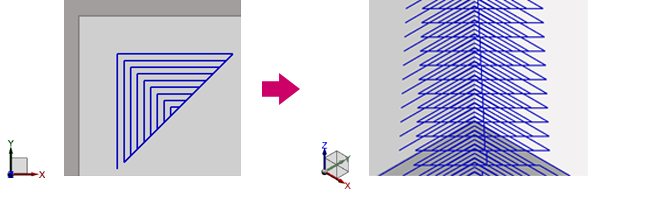
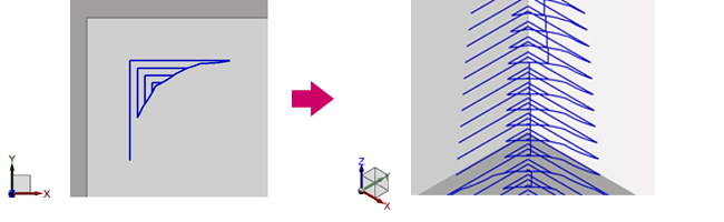
Addition of Plane Z Tolerance Parameter
In add to conventional flat machining,Flat Z tolerance parameter has also been added for contour machining and flat edge machining.
Curve or slope in the process of modeling machining geometry can cause a plane not to be recognized as a plane.
For flat face machining, the Flat Z tolerance parameter allows setting a tolerance for Flat Z.
This allows you to generate a tool path for planes with small curves and tilts.
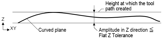
What is Flat Z tolerance?
A curved surface whose amplitude in Z the direction is equal to or less than the specified value is recognized as a horizontal plane.
Tool paths are created with the highest position as the plane in the Z-axis direction inside the curve.
Stock Save in Normal Mode Supported
Stock files for Flat Face/Flat Edge machining can now be saved in normal mode.
For stock files in High Accuracy mode, the uncut portion can be detected with high accuracy but takes longer calculation time when loaded.
You can select this mode when you want to prioritize calculation time.
Add of Work Reference Point Setting to the Path Generation/Batch Screen
The values in [Work Reference Point] are used in [Machine Attitude Drawing] or machine simulations for FF/SIM.
Add of Function to Display Hidden Object
If a registered object is hidden when the Process Setting screen or Machining Setting screen is opened, a message window appears informing that hidden objects exist.
In FFAUT V20, hidden objects can now be displayed temporarily (until the setting screen is closed) by clicking the message window.
It is easier to see the hidden registered objects while setting a process or machining.
Add of Work Model Setting Method in Machine Attitude Drawing
Machining geometry and blank geometry can now be specified as the work model, and machine attitude drawing can be performed without creating an STL model.
Improved Machine Structure Entity Setting in <Machine Parameters>
The parameters of the conventional setting screen have been consolidated to a new dedicated setting screen.
In addition, machine tools of machine structure that could not be set before can now be registered.
It is possible to set up to three linear motion axis and up to three rotational axes.
Setting Example:
- 3-axis machine, 4-axis machine, 5-axis machine, 6-axis machine
- Machines with a tool top direction other than the Z-axis (angle head, etc.)
- Machines with rotary head or rotary table, machines with dual rotary head and table
- Machines with a tilted rotational axis
- Machines with a tilted linear motion axis
Change in Specifications of Insert Statement Parameters
The post process function of FFAUT has been completely changed.
You can output programs for non-FANUC control units such as OSP, Heidenhain, and Siemens.
The setting screen for insert statements has been changed to allow flexible customization of NC output.
Editing with previous insert statements can also be done by the customer, but for more advanced customization, use the post customization service (paid service).
Support for Tool Center Point Control Type2(G43.5)
With Tool Center Point Control Type2, the rotational axis commands independent of the axis configuration are available.
Note that Tool Center Point Control Type2 should be used to specify instructions to machines whose center of rotation is tilted with reference to X/Y/Z axis.
Add of Professional Data Output Function
The interface that outputs data for "Collision Safeguard" and "Work Plan" has been integrated as [Professional data output] function.
【FF/SIM】
Add of Model Transparency Function to [Simulation Info./Cross Section]
This function allows you to see through cross sections of the models of the cut workpiece and machining geometry.
This function is available when the simulation is run in [Create Data (Details)] by setting [Extend (3-5Axis)] mode in Simulation Setting.
Improved Operability of [CL Edit]
- The selection method of functions such as "Moving/Copying", "Delete", "Setting" of [CL Edit] has been changed to the toolbar dropdown list.
The operability has been improved by eliminating unnecessary screen operations. - Add of [CL Edit] Deletion of Block Unit Function
CL can be selected by "Z Level", "Cutting", "Segment", or "Approach" unit to reflect the operator's intent better. Operational errors can be avoided by limiting the CL to be deleted by the element.