Simple & Smart
FFCAM is consistent the concept of “Smart & Simple”, has continued to develop and improve.
Use the FFCAM, anyone can create NC program easily in a short time.
FFCAM can be expected to reduce lead time. So MC will not wait for the NC program.
Easy to use, easy to understand and easy to look.
FFCAM has user friendly interface. So the operators don’t need the manual.
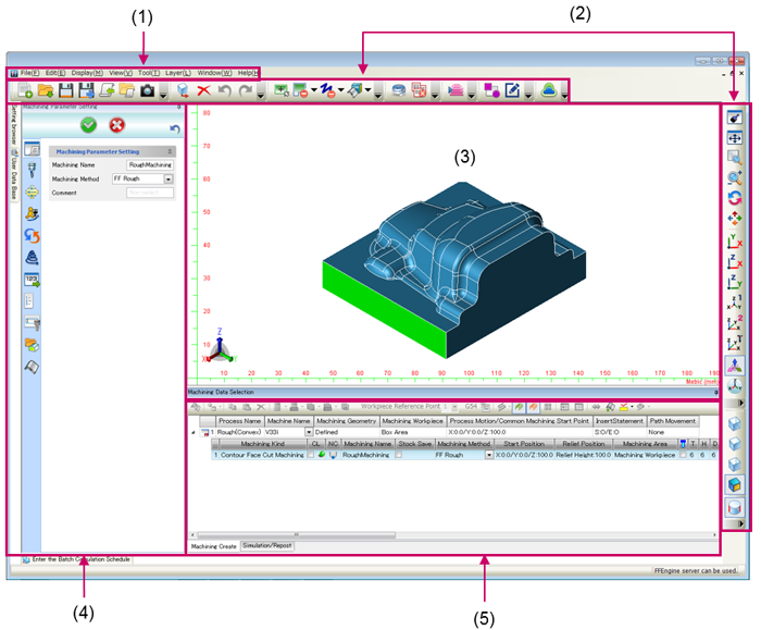
| (1) | Menu bar | Basic menus |
| (2) | Toolbar | Buttons showing each menu icon are displayed side by side. |
| (3) | Graphics window | Geometry or CL data (tool path) are drawn in this window. |
| (4) | Operation panel | The setting screen for each function is displayed. |
| (5) | Main window | he main window is used to manage processes and machining, and to execute simulations or post-processing, etc. The Main window has the following three functions. -Managing processes and machining -Cutting simulation -Post-processing See the “Configuration of Main Window (Common)” on the next page. |
Raise operation rates
The problem at the production field is the yield ratio of industrials by delay of NC program.
Even if the MC is latest one, the operation rates would not be raised by delay of NC program.
FF/cam’s target is the fastest to output the NC program.
Compare with general CAM, FFCAM has less step to generate the NC program.
So MC will not wait for the NC program.
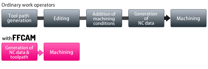
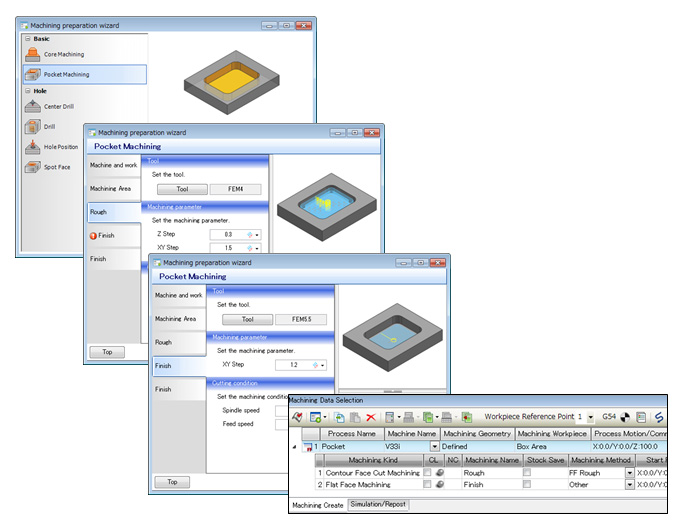
It can be created only by setting four items.
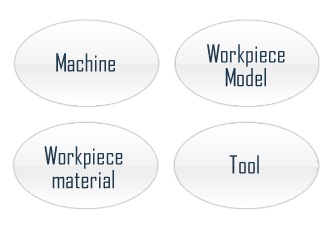
Simplified Entries
FFCAM has normal machining parameters as the template for rough, finish, corner and other machining. It is also available to edit the templates and register it which the customer edited.
Therefore, customer’s original method for machining can also be built up. If the customer uses these templates, a new machining toolpath can be created only by setting following four items.
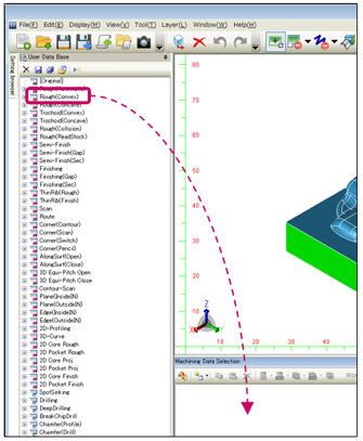
Use Template
Select machining to be set from the [User Data Base] displayed on the left of the screen.
Select one of the machining methods and drag and drop it to the main window to copy the machining.
The initial values of the parameters required to calculate the path are previously registered in the user database. Copying the MC method from the user database allows the path to be calculated with the minimum settings.
Enhancement of database
- With reference to the machining conditions database, Spindle speed, Feedrate and cutting depth are determined automatically.
- It can be shared between the PC on the network.
- Be able to use machining conditions that provided by tool manufacturer.
Machining Conditions Database
Makino has created a database of highly practical machining conditions based on the data obtained in actual cutting tests conducted with Makino’s own machines.
The optimum spindle speed , feed rate and cutting pitch are automatically determined by simply inputting the workpiece material and tools to be used.
This enables even beginning operators to generate workable NC program.
- The database contains over 1,000 types of conditions just for solid ball end mills.
- The conditions are suitable for machining a wide variety of materials, ranging from carburized steels, pre-hardened steels and high-hardness steels to aluminum materials.
- Machining conditions are generated for achieving high efficiency with respect to machining time, machining accuracy and tool life,while taking into account the deflection and deformation that can occur during machining depending on the diameter and length of the tools used.
The spindle speed, feedrate and depth of cut are all determined automatically. - FFCAM has a comprehensive machining condition database for machining in the high-speed range at 40,000 min-1. This facilitates safe machining even with small-diameter tools of less than 1 mm in diameter.
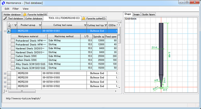
Tool/holder database and cutting condition
database by tool Manufacturers.
Register the tools data and reference cutting conditions offered by tool
manufacturers and tools data used by user frequently.
Process Database
Sharing of technology and know-how
Store the machining process user have created, and use it as original.
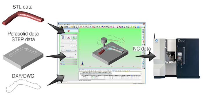
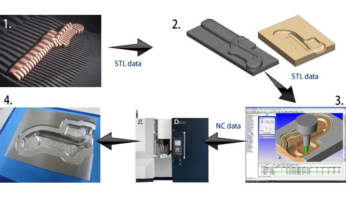
STL Model Machining
It is possible to recognize the model with a mix of polygon and parasolid models as the machining form and generate machining paths.
Using this feature, polygon models which have the advantage of form expression can be used for the overall design and parasolid models which have the advantage of accuracy can be used for parting surfaces and model structure to employ both advantages when designing a model.
KEY features
- Ditized data and design geometries (CG) are output as STL data.
- It can accurately reproduce a shape for which no drawing exists.
- Not select the machining material. The performance of the prototype readily verifiable.
- Smooth processing of huge gigabyte-size volumes of STL data.
Flow of data
Machining Examples
Machining from Digitized data
- Direct scanning on component
- Design by CAD system (Other products).
- Processing of high volume STL data.
- Processing by High Speed and High Accurate MC.
Machining from Medical data
Created using the medical image processing software (other products).
I hope the above is useful to you.
Should you need any further information, please do not hesitate to contact me.
Contact Us By Phone : +81-3-3724-3653
Contact Us By E-mail : software-support@makino.co.jp
Design example using a Photo
The machining by STLCAM for polygons mapped
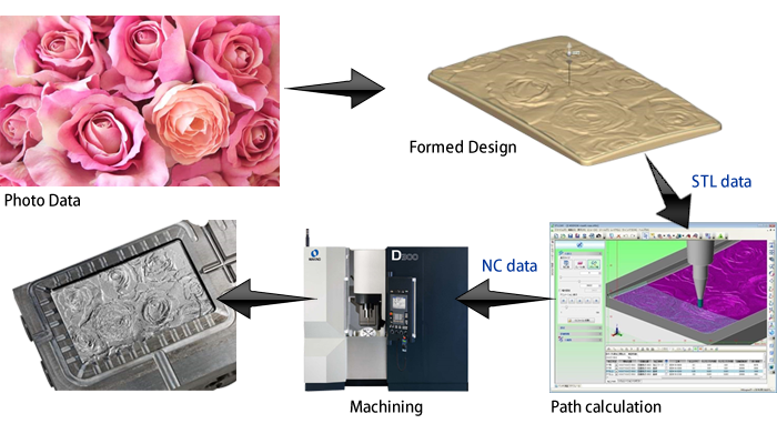
Sakura Relief
Create a metal relief from the photograph of the cherry trees.
For the initial trial, STL data was smaller than now.
| Machine | V33 |
| Material | Material |
| Cycle time | 15h 52min |
| Tool | 4 kinds , 5 pc |
| Size | 100 x 100 |
| STL data size | 79.9MB |
| No. of polygon | 1,677,696 |
Bark scan data
Scanning the ginkgo skin in 3D digitizer scanner (other products).
We were cutting for the reproduction test.
| Machine | V56i |
| Material | PX5 |
| Cycle time | 12h 3min |
| Tool | 4 kinds , 6 pc |
| Size | 370 x 95 |
| STL data size | 1.46GB |
| No. of polygon | 31,456,804 |
Galusha pattern relief
It can output NC-Data for models from an picture(ray scales) by CAD.
| Machine | V22-5XR |
| Material | NAK80 |
| Cycle time | 8h 14min. |
| Tool | 3 kinds , 3 pc |
| Size | D70 x 50 |
| STL data size | 399MB |
| No. of polygon | 8,382,768 |
Leather pattern graphite
It can output NC-Data for models from an picture by CAD.
The realistic texture of the leather can be easily mistaken as the real.
| Machine | V22 GRAPHITE |
| Material | GRAPHITE TTK-8 |
| Cycle time | Cycle time |
| Tool | 4 kinds , 5 pc |
| Size | 75 x 150 |
| STL data size | 26.4.5MB |
| No. of polygon | No. of polygon |
Useful functions for toolpath generation
The operation is very simple, and an advance special knowledge is not required.
A beginners can be easily operated, a significant reduction in model editing time can be expected.
Tool-path Assist
Toolpath Assist allows you to extend the path instead of creating surfaces in CAD and ignore the holes that are in the cutter path.
Since only the motion has to be specified with Toolpath Assist function without creating surfaces, managing machined surfaces for each type of machining is not required.
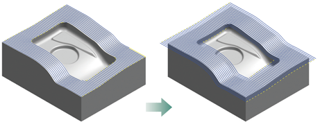
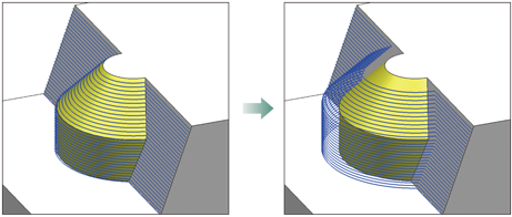
Extension
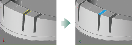
This function is used to extend toolpaths slightly such as for executing sharp corners or enlarging the area to be machined.
Extending the toolpath prevents sloppy corners and avoids leaving tool marks at the boundary of the machining area.
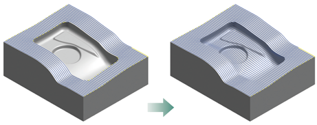
Ignoring Holes
This function creates toolpaths that ignore specified grooves and pockets to be machined later with another tool.
It is handy for dividing the machining area on the basis of grooves or pockets.
Detach from Face
Depending on the machining process, there are faces that you do not want the tool to touch , such as those already finish machined or ones to be machined later.
With this function , such faces can be specified for non-contact with the tool.
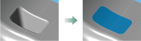
One Click Masking
One-click Masking masks the areas that are not machined during the machining, such that the cutter path is generated only for the required locations.
The geometries prepared with One-click Masking can also be used by setting it for machining geometry or Toolpath Assist.
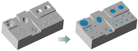
Masking Hole
This function is used to mask grooves, holes and i\nsert pockets to be machined later by EDM.
All types of holes can be masked by simply clicking on the top of a hole.
Bury a Drill Hole
Many drill holes in a part shape can be buried all at one time with this function.
The size of holes to be buried can also be specified This makes it possible to bury just the holes to be drilled and to leave all the holes to be machined with an end mill.
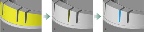
Masking a Notch
This function eliminates notches midway in a face to be machined, thereby creating a simple machining area for which the toolpath can easily be generated.
Plug a section between Two Curves
This function applies a face between two edges.
Function Wizard
The machining procedure is easy even for beginners as the setup wizard guides users through the required CAM settings.
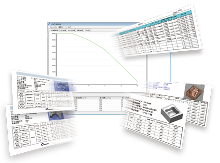
High-accuracy Machining Time
The expected time of processing is output to LST, TCSV and CSV files with considering the acceleration or deceleration by Super GI.4.
What is the “Super GI” control?
This shortens machining times in high-definition milling of dies and molds by 15% on average and by up to 30%.
Super GI realizes its maximum effectiveness especially when machining at high feedrates resulting from higher spindle speeds.
Super GI control further enhances the high-speed performance of Makino machining centers.
- This can be used for only our machining center.
- Canned cycle of Drilling is not supported.
- Simultaneous 4-axis and Simultaneous 5-axis Machining are not supported
Data Output Function for Collision Safeguard
By using this function (data output function for Collision safeguard), the necessary data can be output from FFCAM to Collision safeguard.
With this function, flow of machining from FFCAM to Collision safeguard becomes smooth.
Collision Safeguard
Real time monitoring by before machining.
Collision safeguard reduce the interference dramatically.