FFCAM 2018.x New Function
- The “STL Model Machining function” is now available as a standard function.
- The redesigned User Interface of “Machine Simulator (optional Software)”.
- The “Hairline Finish (optional Software)” machining function supports 5-Axis Simultaneous Machining.
Machining Functions
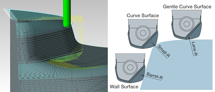
Lens barrel tool is now supported.
The lens barrel tool has gentle R at the bottom and side surfaces.
Therefore, in machining, the step can be set to a larger value than when a ball end mill with the same tool diameter is used, resulting in shorter machining time.
Model top Automatic Recognition Function
This function automatically recognizes the machining geometry vertices and adds the tool path of rough contour machining to its Z level.
This function can be used for “Rough Contour Machining”, “Contour Semi-Finish Machining”, and “Contour Finish Machining”.
Green line:Tool path added by [Model Vertex Auto Recognition] function
Supports Multiple Taper Neck Stages
You can now set a tool shank up to 5 stages.
The tool shape that is closest to the actual tool can be registered, enabling a more accurate interference check of the shank.
1-stage shank

2-stage shank

5-stage shank

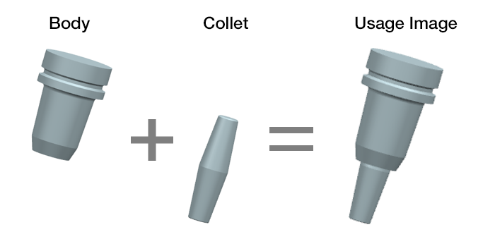
Support for Two Piece Holder
For the holder registration, the holder body and the collet can be used in combination, after separately registering them.
Machine Functions
CL Division Function
In FFCAM2018.2, you can divide the tool path based on cutting time or cutting length so that machining can be continued beyond the service life of the tool.
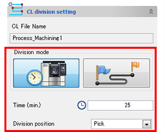
Registers CL data after division to the CL list. The CL data registered is also enabling execution of simulation and repost.
You can create NC data using divided CL data. Also, you can edit the divided CL data.
Removal of Restrictions on Lens Barrel Tool
The following two parameters can now be set for the lens barrel tool added to FFCAM 2018.
- Specification of step height by scallop height
- Along-section machining
Add of Parameters for Specifying Along-Section
A “Scallop height constant motion” function has been added.
In the function, a tool path with constant scallop height after machining is output. This enables machining the side surfaces reducing the gap between tool paths to only the required extent while preventing uncut portions on the flat parts.
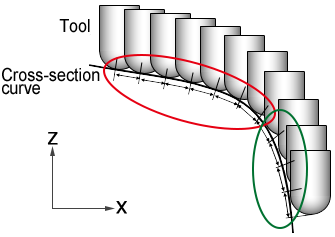
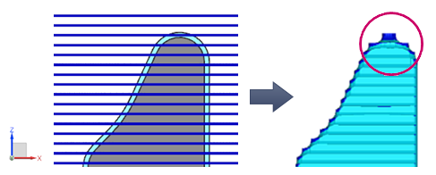
Conventional along-section
The spacing between tool paths on the cross-section is constant.
In the figure below, the scallop height on the machined surface is different for the areas indicated by red and green circles.
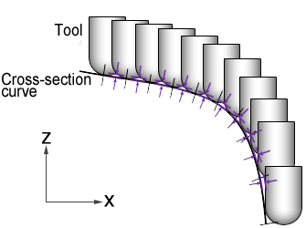
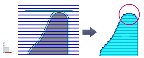
Scallop height constant motion
The scallop height is constant on the cross-section.
The spacing between tool paths are non-uniform according to the inclination angle of the cross-section.
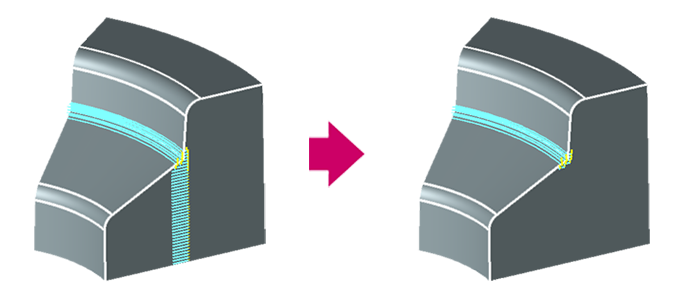
Improvement of Air Cut Path in CR Machining
When a negative finishing allowance is set for contour machining such as fillets etc., tool paths may be created in portions where it is not required.
As a function to prevent this motion, the “Air cut restrict when a negative finishing allowance is set” parameter is added.
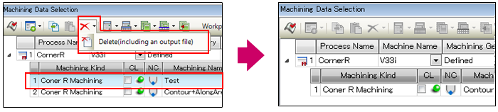
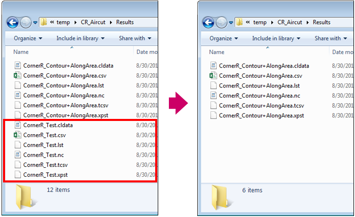
Deletion of Output File While Deleting Process/Machining
When deleting processes or machining on the [Machining Data Selection] screen, files created after calculation can now be deleted together.
As files that are not required is not saved in the calculation result output destination folder, file management becomes easier.
Operation
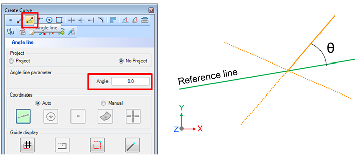
Add of Function for Creating Angle Line
A straight line can be created from any straight line at a certain angle.
Add of Function for Editing Curves
The following functions have been added to the Create Curve function.
You can edit the existing curves.

Divide Curve
Divides a curve into two curves at the boundary curve.

Trim Curve
Trims a curve at the boundary curve.

Trim Curve
Trims a curve at the boundary curve.

Fillet Curve
Inserts a fillet of the specified radius between two curves.
Add of Guide Display Function at the Time of Curve Creation
The following functions have been added to facilitate creation of curves.
- Grid Display/Grid Fit
- Display Binding
- Display Distance
- Display Length
Improvement of the User Data Base Function
- Change in switching method in User Data Base.
Switching between multiple user databases has now become faster. - Change in how to start the setting browser.
- Explanations and pictures are added to the setting browser.
The explanations added to the machining in User Data Base makes it easier to understand the machining details of User Data Base and find an optimal machining method. - Changes in User Data Base.
Improvement of Collision Safeguard Data Output Function
Support for Professional 6.*
* Professional 6 is an advanced set of control technology engineered to remove time and energy in production.
Specification of Offset Curve Direction
With the Offset Curve function, you can now specify the direction before executing offset.

Preview of the offset result
When you click on the curve to offset, an arrow indicating the offset direction is displayed along with the preview of the offset curve.
Reversing the offset direction
When you click on the arrow marker, the offset direction is reversed.
Improvement of Curve Fillet
Fillets can now be defined for curves and rectangles created together.

Before
All the curves will be selected when you click on a curve and fillets cannot be created.

FFCAM2018.2
You can select individual curves even when curves are created together, and fillets can be created.
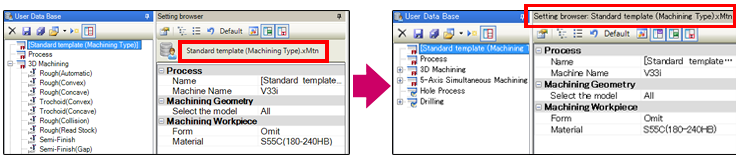
Improvement of Setting Browser
Display of Template Name on Title Bar
Since the template name display is compact, the [Setting browser] screen can be used widely.
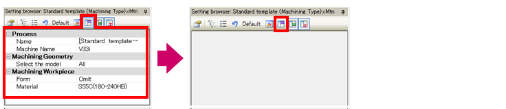
Display Function for Parameter List
You can now toggle between display and hide for the parameter list of the [Setting browser].
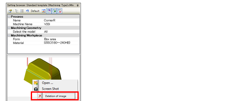
Deletion of Image in Setting Browser
You can now delete images registered in the [Setting browser].
Option
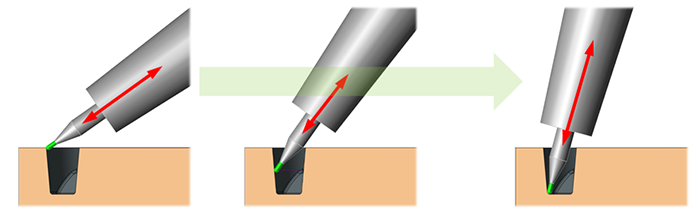
Simultaneous 5-axis motion support for Hairline Finish
Hairline pattern equivalent to horizontal surface even on a slope will be given due to oscillation by the cutter paths with tool axis direction.
Surface finish quality improvement and shorten the overhang length of the tool will be given because machining can be done with the optimal direction.
Refreshed the User Interface of the Machine Simulator.
Dramatically improved the simulation and setup functions.
It improved the visibility and operability, and to improve ease of use.