The most distinguishable character of FFCAM is the high-quality machining toolpath.
The necessary setting for FF machining as tilting infeed are automatically added without settings by the operator.
Rough Machining
Contour Rough Machining
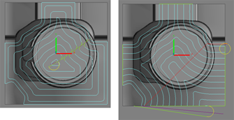
In Rough Machining, Create the cutter path to reduce the tool load.
Automatically changes inward or outward motion to match the machining geometry.
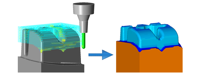
Toolpath without collision
A toolpath is generated only for the portions that can be machined with the specified tool overhang length.
This function generates safe toolpaths without any holder interference even for workpieces with deep cavities and complex geometries
Half Pitch Shift
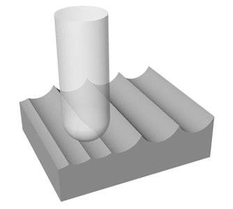
The toolpath that is keep tool load produces stable machining. So it extends tool life.
The toolpath is shifted for the half pitch from previous one.
By using “Half Pitch Shift” function, tool chipping is prevented by sudden change of tool load and a tool life is extended.
Automatic Insertion of Corner Radii
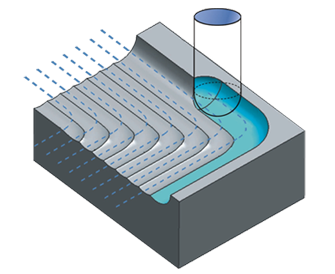
Corner radii are automatically inserted in the corner portions of the toolpath.
This function prevents tool damage due to sudden changes in the tool load.
Semi-Finish Machining ,Finish Machining
Contour Projection Machining
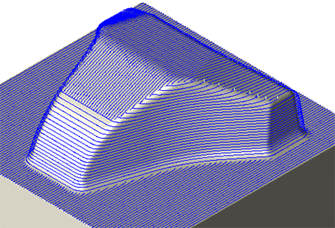
It switches between contour machining and projection machining automatically depending on the inclination angle of the geometry surface.
Finishing of complex geometry can be automated efficiently.
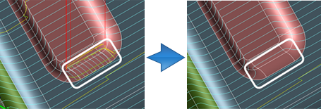
【High function mode】
High function mode allows contour machining and projection machining locations to be specified arbitrarily on a surface by surface basis.
Moreover, you can set the projection direction for each area arbitrarily.
Contour Z Spiral Machining
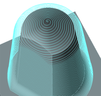
Make a spiral tool path based on the tool path of contour machining.
Optimized for high-precision machining. Especially effective for small mold machining like lens or electrodes.
Contour Finish
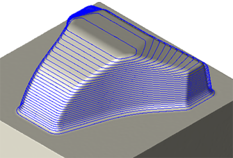
Creates contour paths to form uniform steps on the specified cross-section.
This results in a highly uniform machined surface that readily facilitates additional machining with fine tools in subsequent operations.
Corner R Machining
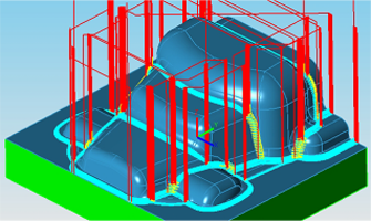
This toolpath is to find the machining remain from a former machining automatically and creates appropriately.
Both of contour and along the surface movement can be applied for areas with different pitches.
3D Equi-Pitch Machining (Close)
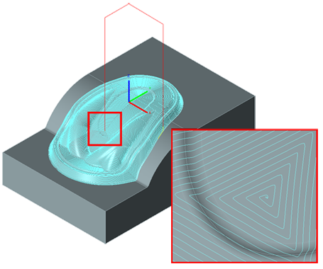
Make a equally tool path fit on the geometry that was based on setting one group of closed curves.
For geometry machines by regular inward/outward motion.
Curve lines and edges of solid models are required as different elements.
3D Equi-Pitch Machining (Open)
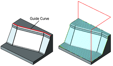
It is uniformly processed according to the selected open loop curve.
It is useful for shapes with sudden rises and falls.
Curve lines and edges of solid models are required as different elements.
3D Curve Machining
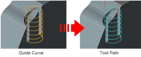
[3D curve machining] sets the curve as the target for machining and generates a tool path along the curve.
“Every curve” shorten the machining time.
Because it is move less between the guide curves and it is intensively machining one of the guide curves.
Along Surface machining
FFCAM creates smooth toolpath to several surfaces.

Gap Machining
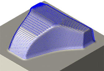
FFCAM creates toolpath that is few machining remain at smooth surface.
Contour Gap Machining is notably effective for die cast dies with their highly convex-concave geometry.
Corner Edge (Contour Machining and Scan Machining)
The corner edges become sharp.
It is effective for parting line, slide and edge.

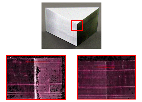
2D machining from 3D model
Flat Face Machining
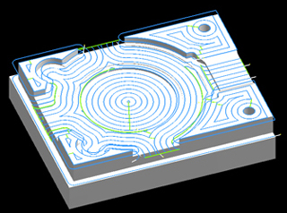
FFCAM automatically detects the flat areas of the workpiece geometry and generates toolpaths only for those surfaces.
Flat Edge Machining
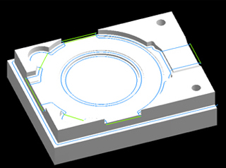
FFCAM automatically detects the flat areas and section edges of the workpiece geometry, and generates toolpaths only for the edges of the flat surfaces.
2D Profile Machining
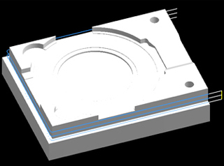
FFCAM generates toolpaths on simple profile lines. This function is also used to generate a path for the tool radius offset code。
It is also available only 2D.
Drilling
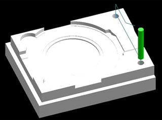
FFCAM supports drilling with tools such as drills, taps, reamers, boring tools, and chamfering cutters.
It is also available only 2D.
Trochoidal Machining
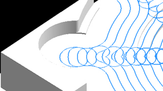
Trochoidal (spiral) motion is performed where the cutting load increases.
The trochoidal machining function enables high-speed machining with end mills.
Core / Pocket Contour-step Machining

Only specify the outline and parameter, can make a toolpath of Contour-step machining on core・pocket geometry of 2 – 2.5D.
It is also available only 2D.
Other
Fast Calculation (Multi Thread)
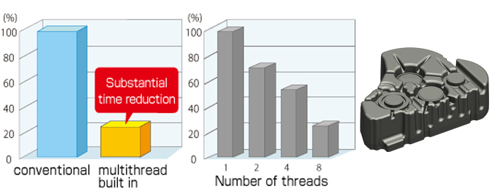
Reviewed algorithm and utilization of multithread technology shorten tool paths calculation time to 1/3 of conventional time.
Efficient implementation is possible in NC program generation for large shape or sophisticated shape that require huge volume of calculations.
Case : Gear-case cover
450x450x130mm
1800KB (Parasolid)
Contour machining
Intel(R)Xeon(R)CPUE5540 @2.53GHz (2 processors)
48GB mounted (OS recognition 2.75GB)
Optimization of tolerance values
Smooth Machined Surfaces
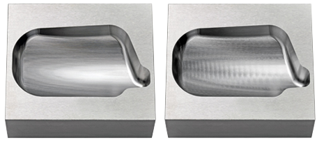
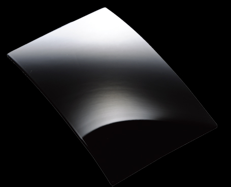
Setting smaller tolerance values in NC programs results in smooth machine motions which produce smooth machined surfaces.
Smaller tolerances also mean smaller angle changes between NC blocks.
So the machine can decelerate less at corners, which has direct effect to reduce the machining time.
Left:
Tolerance values ±0.0001 mm
Right:
Tolerance values ±0.001 mm
Path Analyzer
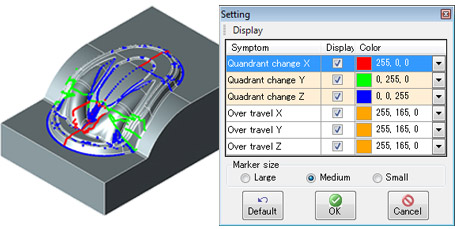
Using find root causes of failures,such as lines on machined surfaces caused by characteristics of the machine or programs.
By using this before machining, avoiding such failures is expected.
Machining Area Automatic Setting
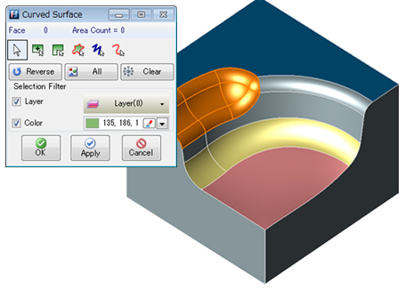
When a machining selection condition is registered in the user database and machining is copied from the user database, areas that match the condition can be set automatically.
Dual Monitor
Support is provided for viewing with two connected monitors.
The model screen and machining setting screen can be displayed on separate monitors for allowing use of a wider screen area.


